I. Printer Board Definition
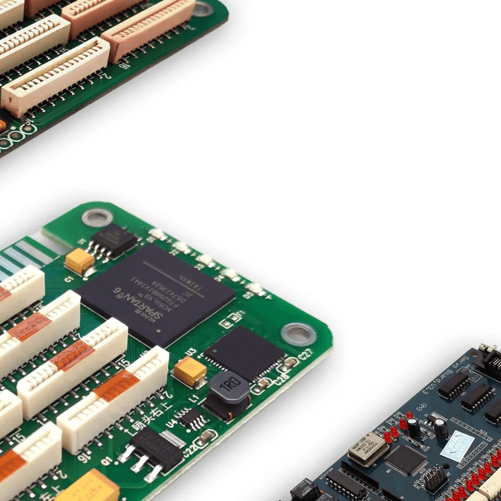
A printer board is a type of inkjet printing control system for inkjet printing. It's a custom-designed PCB for inkjet printing equipment. It comes with embedded control system software and desktop computer control software. It implements various operations during the inkjet printing process, including dot algorithm generation, motion control, color management, printhead control, and high-speed processing of large amounts of data.
Inkjet printing is accomplished by the control system processing data and issuing commands to various other systems. These systems are then driven to execute inkjet printing.
The control system is the core module of inkjet printing equipment, and the quality of its algorithms and control directly affects the performance of the inkjet printing equipment. Improvements in inkjet printing equipment performance are reflected in the fineness of the printed ink droplets, the level of color gradation that can be printed, the number of colors, image sharpness, printing speed, width, stability, and the range of substrates that can be printed. All of these rely on improved board performance.
The control system is a comprehensive product that integrates circuit design, algorithm programming, motion control, color management, and other functions. It uses a board as a carrier and is embedded with system software with functions such as the dot algorithm, motion control, color management, printhead control, and high-speed processing of large quantities of data. It is equipped with computer desktop control software and an integrated industrial inkjet control system to provide core modules for industrial inkjet printing equipment manufacturers.
II. Basic Functions of the Printer Board
1. Receive and interpret data from RIP software
Printers typically use KCMY ink. During RIP processing, the RIP software represents all colors using KCMY data. Different colors have different KCMY values. After receiving the RIP data, the printer board controls the corresponding printhead channels to discharge ink according to the ink sequence settings in the PM software. The PM ink sequence settings must correspond to the order of ink in the printheads.
2. Powering Certain Components
The board provides power to electronic components, primarily serving two functions:
① Supplying operating voltage to the components, enabling normal operation.
② Supplying signals to the components for control.
For the raster decoder and ink pump, the board provides operating voltage.
For the motor and UV lamp, the board provides a signal voltage for control.
The board also supplies power to the printhead, providing operating voltage, and outputs control signal voltage to control ink jetting.
③ Receive feedback signals and perform control based on the information.
The board primarily receives feedback signals from the raster decoder, secondary ink cartridge float, stopper, and anti-collision switch. It receives feedback signals from the raster decoder to control the X-axis print position, receives signals from the secondary ink cartridge float to control ink supply, receives feedback signals from the stopper to control movement, and receives signals from the anti-collision switch to control movement.
III. Selected Board Suppliers
1. GIS: Global Inkjet Systems, UK
2. Meteor (TTP)
3. Beijing Boyuan Hengxin Technology Co., Ltd.
4. Shenzhen Hanson Software Co., Ltd.
5. JetBlue Printing Technology (Suzhou) Co., Ltd.
6. Beijing Lanyin Technology Co., Ltd. (Shanghai Tongyin Inkjet Technology Co., Ltd.)
7. Guangzhou Senyang Electronic Technology Co., Ltd.
8. Wuhan Jingfeng Technology Co., Ltd.
9. Shanghai Yeshuo Digital Information Technology Development Co., Ltd.
10. Shenzhen Weiliyin Technology Co., Ltd.
11. Shanghai Rongyue Electronic Technology Co., Ltd.
Ⅳ. Board Design
Designing a printhead driver board is a complex task requiring both technical expertise and experience.
The driver system must be capable of generating a suitable high-voltage waveform containing high-quality trapezoidal pulses across a range of jet loads. The system must support multiple trapezoidal pulses of varying amplitudes within a single waveform, and these waveforms must be programmable, allowing for optimization of the waveform structure for different applications or inks. Finally, the data path circuitry must promptly update the switch status of the driver chip just before each pulse within the waveform occurs.
To ensure that all ink droplets are ejected with the correct size and velocity, the drive circuitry must generate very precise waveform shapes. These waveforms must account for several complex factors:
- If a droplet is ejected by a pulse at the beginning of a waveform, it will emerge from the nozzle earlier.
- Small droplets remain in the air longer than larger ones (while the print media is moving).
- Due to different waveform pulse sizes, some ink droplets travel faster than others.
- Ink droplets may collide with and merge with other droplets during flight.
- The distance between the nozzle surface on the printhead and the print media surface varies.
- Different ink types require different waveforms.
The driver board will have a power amplifier for each nozzle row, allowing each row of nozzles to apply a different waveform to compensate for the differences between nozzle rows. In contrast, cheaper, simpler driver boards only need to switch between two voltage levels. For best results, each waveform pulse that generates a sub-droplet should have a different pulse shape. For example, ejecting an ink droplet requires more energy for the first time than for the second time because the piezoelectric element is already oscillating. This means that ideally, the hardware generating the voltage waveform should be able to support analog pulses of varying shapes. Clumsy driver boards attempt to bypass these complex requirements and simply generate waveform pulses by switching between two voltage levels.
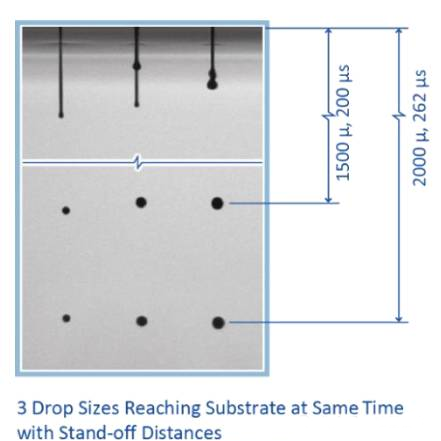
By independently controlling the timing of each pulse and being able to match any pulse segment to a waveform with a specific droplet size, more powerful control can be achieved on top of simple multi-pulse operations.
- The printhead driver and software generate digitally defined, multi-pulse complex waveforms, which the printhead then uses to generate timed ink droplets of varying sizes, landing them at precise locations on the moving media.
Generates digitally defined, multi-pulse complex waveforms, and then uses selected pulses within the waveform to generate ink droplets of varying sizes, landing them at precise locations on the moving media.
- Includes multi-pulse amplifier and multi-bit data encoding and decoding capabilities
- Capable of generating trapezoidal pulses over a range of injection loads, supporting multiple trapezoidal pulses of varying amplitudes within a single waveform
- Updates the switch status within the driver chip immediately before each pulse within the waveform
- Provides user-programmable waveforms optimized for each application or ink.
- Each row of nozzles is equipped with a power amplifier, rather than simply switching between two potentials.
- Supports different analog pulse shapes for each sub-droplet within the same waveform.
- Offers intuitive hardware and software integration and global customer support.